Sizing a BESS for an industrial plant requires more than simply choosing a battery based on capacity. BESS sizing for industrial plants involves determining both the power rating in MW and the energy capacity in MWh based on the facility’s load profile, operating requirements, peak demand and intended application. Whether the goal is peak shaving, backup power, solar integration or multiple applications, the right BESS size should be based on how much power is required and how long that power must be delivered.
For peak shaving, a practical starting point is:
Required BESS power (MW) = Existing peak demand − Target grid demand
Then:
Required usable energy (MWh) = BESS power (MW) × required discharge duration (hours)
But that is only the starting point. Final BESS sizing should also consider the plant’s interval load profile, tariff structure, battery operating limits, efficiency, degradation, recharge opportunities and the specific objective of the project.
How to Approach BESS Sizing for Industrial Plants
A BESS has two fundamental capacity dimensions.
| Parameter | What it tells you | Example |
| Power | How much electricity can be delivered at once | 1 MW |
| Energy | How much electricity can be stored | 2 MWh |
| Duration | How long the battery can deliver its rated power | 2 hours |
| C-rate | Relationship between power and energy | 0.5C |
For example, a 1 MW / 2 MWh BESS could theoretically deliver 1 MW for 2 hours, subject to the system’s operating limits.
This distinction matters because two plants can require very different systems even if their peak demand is identical.
A factory with a short 15-minute demand spike may need high power but comparatively little energy. A facility with a sustained three-hour peak may require substantially more MWh.
Step 1: Define the Use Case for BESS Sizing for Industrial Plants
Before calculating MW or MWh, define the primary use case.
Peak shaving
The objective is to reduce the plant’s grid demand during high-load periods.
The sizing question is:
How many MW must the battery discharge to keep grid demand below the desired threshold?
Backup power
The objective is continuity during a grid outage.
The sizing question becomes:
How much critical load must remain powered, and for how long?
Solar self-consumption
The battery stores surplus solar generation and releases it when the plant needs electricity later.
Here, the sizing depends on the surplus solar profile and the plant’s consumption profile.
Multiple applications
A BESS may be expected to perform more than one function. For example, an industrial plant could use it for peak shaving during normal operation and reserve part of its state of charge for backup.
That makes the sizing exercise more complex because the system has to satisfy multiple operating constraints.
Step 2: Use Load Profiles for BESS Sizing for Industrial Plants
This is one of the most important steps in BESS sizing.
Do not size a BESS only from:
- monthly electricity consumption;
- sanctioned load;
- transformer rating;
- or a single maximum-demand number.
Those figures do not tell you how the plant’s load changes during the day.
Ideally, obtain interval data showing the plant’s demand over time. Fifteen-minute data is particularly useful for many commercial and industrial applications, but the appropriate interval should match the applicable meter and tariff structure.
The load profile should help answer:
- What is the maximum demand?
- When does it occur?
- How frequently do peaks occur?
- How long do they last?
- Are the peaks predictable?
- What is the minimum demand?
- When can the BESS recharge?
- Does production create repeatable load patterns?
- Is solar generation present?
- Which loads are critical during an outage?
A simple monthly bill cannot answer all of these questions.
Step 3: Calculate the Required BESS Power in MW
For peak shaving, start by defining the maximum grid demand you are willing to allow.
Formula
Required BESS power = Existing peak demand − Target grid demand
Example
Assume an industrial plant has:
- Maximum demand = 3 MW
- Desired grid-import limit = 2.5 MW
Therefore:
Required BESS power = 3 MW − 2.5 MW
Required BESS power = 0.5 MW
The battery and PCS therefore need to be capable of supplying at least approximately 500 kW during the relevant peak event.
However, the calculation should not stop there. The engineer should verify whether the 500 kW requirement occurs continuously, how frequently it occurs, and whether additional operating margin is required.
Step 4: Calculate the required energy capacity
Once the required power is known, determine how long the BESS needs to sustain that output.
Formula
Required usable energy = Required BESS power × discharge duration
Suppose the plant’s demand remains above the 2.5 MW target for approximately 1.5 hours.
The calculation is:
0.5 MW × 1.5 hours = 0.75 MWh
So the plant requires approximately 0.75 MWh of usable discharged energy for this simplified scenario.
This does not automatically mean that a 0.75 MWh nameplate battery is sufficient.
Step 5: Convert usable energy into nameplate battery capacity
The battery cannot necessarily use 100% of its nameplate energy in every operating cycle.
Sizing must consider factors such as:
- allowable depth of discharge;
- discharge efficiency;
- battery degradation;
- minimum state of charge;
- operating reserve;
- temperature;
- auxiliary consumption;
- warranty requirements;
- and the required end-of-life performance.
Worked example
Assume, purely for illustration:
- Required delivered energy = 0.75 MWh
- Maximum usable depth of discharge = 90%
- Discharge efficiency assumption = 95%
- End-of-life capacity factor = 80%
Then:
Required nameplate energy ≈ 0.75 ÷ (0.90 × 0.95 × 0.80)
Required nameplate energy ≈ 1.10 MWh
Therefore, the initial calculation suggests that a system around 0.5 MW / 1.1 MWh could be evaluated.
This is an engineering example, not a product recommendation. Actual system sizing must use the selected battery’s guaranteed operating parameters and the project’s duty cycle.
Notice the difference:
0.5 MW / 0.75 MWh represents the simplified required power and usable energy.
~0.5 MW / 1.1 MWh represents an illustrative nameplate requirement after applying the stated assumptions.
That distinction is important when comparing BESS quotations.
Step 6: For accurate sizing, use the complete load profile
The simple peak-duration calculation is useful for an initial estimate, but a real project should go further.
For interval data, the energy required above the target demand can be estimated by summing the excess load during each interval.
For example:
Required energy ≈ Σ [(Actual load − Target load) × interval duration]
for all intervals where actual load exceeds the target.
If the data is recorded every 15 minutes, each interval represents:
0.25 hours
Suppose one interval records:
- Actual demand = 3.0 MW
- Target demand = 2.5 MW
The battery would need to provide:
(3.0 − 2.5) × 0.25 = 0.125 MWh
The calculation is then repeated for each interval above the target.
This approach gives a much better representation of the battery’s actual energy requirement than simply multiplying the monthly maximum demand by an assumed number of hours.
A detailed simulation should also track the battery’s state of charge over time. A battery cannot discharge indefinitely without recharging, even if the total calculated MWh appears sufficient.
Step 7: Size the PCS and battery together
The battery and Power Conversion System (PCS) cannot be treated as completely independent components.
The PCS determines how much AC power can flow between the battery and the electrical system.
For the earlier example:
- Required peak-shaving power = 500 kW
- Required usable energy = 750 kWh
The system therefore needs a PCS capable of delivering at least the required power under the project’s operating conditions.
The resulting power-to-energy relationship is also important.
For example:
500 kW ÷ 1,100 kWh ≈ 0.45C
This indicates that the illustrative battery is being discharged at roughly 0.45C at the specified operating point.
The selected battery, PCS and thermal-management system must all be capable of supporting the intended duty cycle.
Backup-power sizing uses a different logic
Peak shaving and backup should not be sized in exactly the same way.
For backup, start with the critical loads that must continue operating during an outage.
Example
Assume a plant has:
- Total facility load = 2 MW
- Critical load = 600 kW
- Required backup duration = 2 hours
The basic usable-energy requirement is:
600 kW × 2 hours = 1,200 kWh
Therefore:
Required usable energy = 1.2 MWh
The nameplate requirement must then account for the selected battery’s operating window, efficiency, degradation allowance and reserve requirements.
The key point is that a plant with a 2 MW total load does not necessarily require a 2 MW BESS for backup if only 600 kW of the facility is designated as critical.
That can materially change project economics.
Solar + BESS requires another layer of analysis
If the industrial facility already has or plans to install solar, BESS sizing should consider both generation and consumption profiles.
For example, a factory may produce substantial solar energy during the afternoon but experience significant electricity demand later in the day.
Instead of allowing surplus solar energy to go unused or exporting it under less attractive conditions, the BESS can potentially store energy and discharge it when the facility needs it.
The calculation therefore needs:
- solar generation profile;
- plant demand profile;
- export limits;
- grid-import requirements;
- battery charging capacity;
- battery discharge requirements;
- and the applicable commercial/tariff structure.
India’s Ministry of New and Renewable Energy currently lists an advisory on co-locating energy storage systems with solar projects, alongside other ESS policies and guidelines.
What makes BESS sizing different in India?
The technical sizing principles are universal, but the commercial case is highly dependent on the Indian project’s tariff and grid conditions.
For an industrial consumer, the financial value of storage can depend on factors such as:
- demand-related charges;
- time-varying tariffs where applicable;
- sanctioned/contract demand;
- solar generation;
- DG operation;
- production schedules;
- outage frequency;
- grid constraints;
- and the applicable state electricity-regulatory framework.
India has also established a national framework for promoting Energy Storage Systems. The Ministry of Power published the National Framework for Promoting Energy Storage Systems in August 2023, outlining policy and regulatory measures intended to support the development and deployment of energy storage in the country.
The policy environment has continued to develop. MNRE’s current ESS policy listing includes 2025 measures covering BESS viability-gap funding, inter-state transmission-charge waivers for ESS and other storage-related initiatives.
For this reason, an industrial BESS business case should use the tariff and regulatory conditions applicable to the specific state and project rather than applying a national “₹/kWh savings” assumption.
Common BESS sizing mistakes
1. Sizing only from monthly electricity consumption
A plant consuming 500 MWh per month could have a very different load profile from another plant consuming the same amount.
Energy consumption alone does not tell you the required BESS power.
2. Confusing MW with MWh
A 1 MW battery and a 1 MWh battery describe different characteristics.
One tells you about power. The other tells you about energy.
3. Assuming peak demand lasts for one hour
A maximum demand event might last minutes, an hour or several hours.
The actual load profile should determine duration.
4. Ignoring recharge requirements
If a BESS discharges during one peak event, it may need sufficient time and power to recharge before the next event.
5. Ignoring degradation
A system that meets the requirement on day one may not provide the same usable capacity years later.
The project’s required end-of-life performance should therefore be part of the sizing exercise.
6. Oversizing without an economic reason
More MWh does not automatically mean greater savings.
If the additional capacity is rarely used, the additional capital expenditure may not generate an adequate return.
7. Sizing the battery without the PCS
The battery may contain substantial energy, but the PCS determines the AC power that can actually be delivered.
Both need to be evaluated together.
A practical BESS sizing checklist
Before requesting a technical proposal from a BESS supplier or EPC, prepare:
| Data required | Why it matters |
| 12 months of interval load data | Identifies peak patterns |
| Maximum demand | Establishes peak-shaving baseline |
| Target grid demand | Determines required MW |
| Peak duration | Determines required MWh |
| Production schedule | Identifies recurring operating patterns |
| Tariff structure | Determines potential financial value |
| Solar generation data | Required for solar + BESS sizing |
| Critical-load list | Required for backup sizing |
| DG capacity and operating pattern | Helps evaluate diesel displacement |
| Transformer/switchgear details | Determines electrical integration requirements |
| Available installation area | Influences system configuration |
| Required project life | Influences degradation assumptions |
| Expansion plans | Helps avoid premature undersizing |
The more complete the input data, the less the final design needs to rely on assumptions.
Real-World BESS Sizing Example for an Industrial Plant
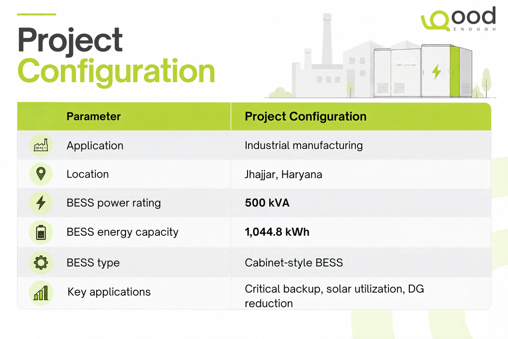
The principles of BESS sizing become clearer when applied to an actual industrial installation. GoodEnough Energy deployed a 500 kVA / 1,044.8 kWh Cabinet-Style Battery Energy Storage System (BESS) at an automotive precision components manufacturing facility in Jhajjar, Haryana.
The facility had multiple energy requirements, including critical backup, solar energy utilization, and reducing dependence on diesel generators and UPS systems. These operational requirements are important inputs when determining the appropriate BESS power and energy capacity for an industrial facility.
This example illustrates an important principle of BESS sizing for industrial plants: the required system capacity depends on the facility’s actual electrical requirements and intended applications rather than on a standard battery size.
For this installation, the BESS was used to provide reliable critical backup, improve solar energy utilization, reduce dependence on diesel generators and support reduced UPS dependency.
The project demonstrates why industrial BESS sizing should consider more than peak demand alone. Load characteristics, critical loads, backup requirements, solar generation and existing power infrastructure all influence the final system configuration.
Conclusion:
BESS Sizing for Industrial Plants
A robust BESS sizing calculation starts with the plant’s objective and actual load profile.
For peak shaving, determine the required MW from the difference between actual demand and the desired grid-import threshold. Then determine MWh from how long the BESS must sustain that reduction.
From there, convert usable energy into an appropriate nameplate capacity by accounting for operating limits, efficiency, degradation and reserve requirements.
For backup, size around the critical load and required autonomy. For solar + BESS, model generation and consumption together.
Most importantly, treat the initial calculation as a design starting point, not a final procurement specification. Final BESS sizing should be validated through detailed load-profile analysis, electrical studies, tariff modelling, battery/PCS specifications, operating simulations and project economics.